


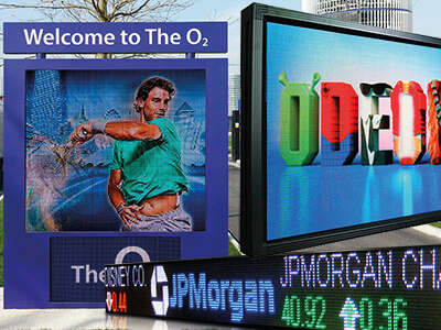
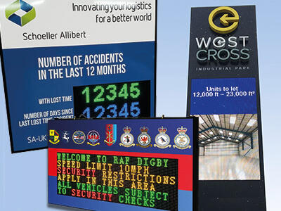
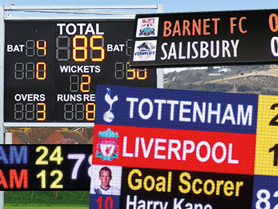
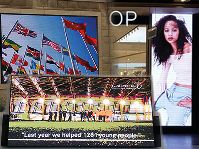
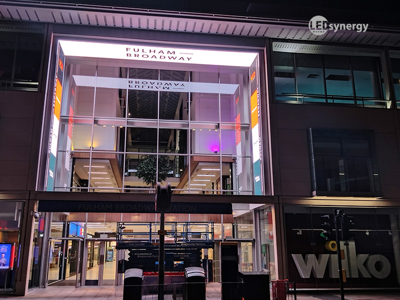
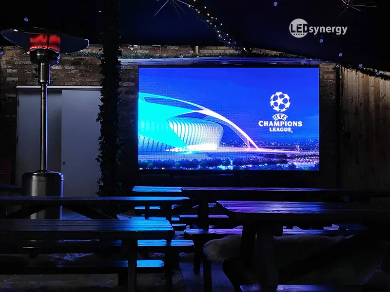
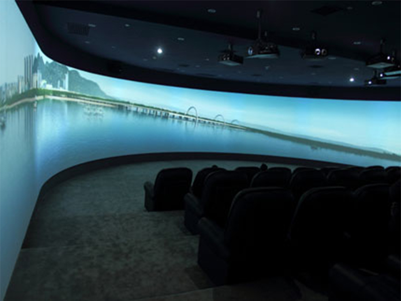
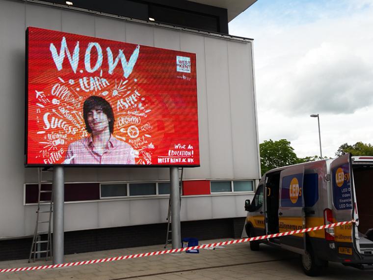
High Quality Bespoke LED Screens & Scoreboards In The UK
Designed & Manufactured in the UK
With over 40 years' industry experience, LEDsynergy is the leader in the LED display market. With our fusion of good design, high quality LED digital display screens and cutting-edge technology at affordable prices, we're confident that you won't be disappointed by our LED products or customer service.
Need Help with LED Displays? Get in Touch: 01264 30 30 30


All you need to know about
LED Displays
A lot of our customers start their journey into electronic LED display boards without much knowledge of the product and the potential.
We have put together the definitive guide to electronic LED displays to aid your decision-making process.
Download the Guide
Very pleased at Selsey Cricket Club, with our new LedSynergy Scoreboard. Great support in helping setting it up. 5 stars.
Ricky Halpin
Selsey Cricket Club

 Neil Marchant28/03/2024Fantastic service from the initial communication, site survey to delivery and installation. Engineers on the day of installation were very professional with a thorough handover.
 J Mousah09/03/2024LEDSynergy was outstanding in supporting us through the procurement and installation of our new Screen. 5Stars AAA+
 Brian Marshall07/03/2024LED Synergy installed 2 safety information signs for us yesterday and we were very impressed with the service. We had a couple of issues with our network communicating with the signs, but they persevered to find a solution and all was resolved thanks to their knowledge and patience. I have no hesitation in recommending them and would definitely use them again.
 Mark Brooks29/02/2024Great company to work with, very good at communication & quality goods supplied would definitely recommend giving them a try especially for something out of the ordinary.
 kwasi bentil23/02/2024Good services and was really impressed with installation team on site. They were easy to deal with and will use them again.
 Freya Powley22/02/2024Amazing service and staff are so helpful I recommend!
 Daniela Coultas22/02/2024Have recently used LEDsynergy's services for a scoreboard. Absolutely loved the end result! They were extremely professional and friendly. Would certainly highly recommend their services to anyone going forward.
 Stevie Pearce21/02/2024A fantastic company to work with, high quality installations, serving many different industries with great attention to detail. Some of the installations really are quite spectacular!
 Ella Powley21/02/2024I have been a customer of LEDsynergy for a while now and I am very happy with their services and products. The staff in particular are extremely friendly and helpful and listened to all my needs and preferences. They also provided me with guidance and support by answering all my incessant questions 😅 I will definitely continue to use them in the future 😁
 lucas Gas21/02/2024Great company to deal with. Response was fast and a very smooth process from start to finish unlike some of the larger national companies I have dealt with it's got a family business feel. Great work team and a special mention to Liz who owned the communication on the project from start to finish Highly recommend Thanks